My theory of writing is that with a clear outline, revision, and peer review a basic piece of writing can become excellent. With a clear outline, you will be able to map out what you want to write and gather your thoughts before you actually write the paper. After writing the paper you should review and reflect on what you wrote and how you can improve it. Doing this multiple times will improve your writing by helping you reword sentences to make it, fixing grammatical issues, and adding any additional information if needed. Peer review is also very helpful to your writing because it brings another perspective to it. This can help you change your writing to fit a certain perspective. Peer reviewing also can be useful for grammatically checking the writing.
Coming into this class my writing was very below average. I did not put much thought into my writing and just focused on finishing the task. My theory of writing was just to finish the task and to make sure my grammar was correct. Although making sure my grammar was correct is important to writing, I never checked to see if my sentences were phrased correctly or if they made sense. Through peer reviewing and self revising I was able to edit my writing so that the sentences were clear and concise. Peer review was especially helpful in the group project, innovation proposal since my group members helped me review my part of the assignment. Also, I would never manage my time when doing an assignment which made it difficult to get it done efficiently. The technical description assignment taught me to create an outline before writing anything since it will help organize my thoughts. This made it easier to manage my time since I was able to think of what to write before I actually wrote it.
I have developed my theory of writing by implementing things like tone, language, genre, audience, and purpose into my writing. When revising my writings I made sure that the tone was set to what the task asked for. For example in my Rhetorical analysis, I had to use a professional and informative tone because it was reviewing a professional lab report. To set the correct tone I had to use the correct language based on the genre of writing as well. In my very first writing assignment for this class, I had to write a letter to the teacher about myself. So for this assignment, I used words that are more formal since I am writing to my professor but I was more casual in writing it because I was telling her more about myself and what I want to do in the future. For the technical description assignment, I used a descriptive and informative tone because I was describing the parts of a skateboard and their functions. I also did the same when writing the innovation proposal since I had to describe an innovation I wanted to make. The audience and purpose also matter a lot when you write something because you need to write in a certain way to appeal to the audience. In the rhetorical analysis, the audience is people who are interested in reading a lab report and the purpose is to inform them if this lab report follows the basic structure of a lab report and if it’s worth reading. The audience in my technical description are people who want to learn about how a skateboard is made, and the audience for the innovation proposal are people who want to learn about possible solutions to electronic noise.
Through this course, I learned to locate research resources in the CCNY library database when doing my rhetorical analysis. I also referred to many other sites in my technical description assignment which helped me gain information on my topic. I used the different websites and articles by paraphrasing and quoting from the text. When I used these sources I had to cite them because they need to receive their credit for their work. This was very important because it would help me avoid plagiarism in my assignments.
This course has changed my theory of writing from when I first started this class because it helped me develop my writing to make it better. I learned to make a clear outline of what I want to write, self-review my writing to fix and edit my writing, and have a peer look through my writing to give me another perspective of the writing. I also learned that the tone and language of my writing should reflect what my audience is. Also learning to use the CCNY database was very useful since I can use it in my future classes when I need to find credible articles for assignments. Giving credit to these articles is very important since it’s their work and not mine, I’m only using their work to support my claims. My writing has come a long way since starting this class and has improved tremendously.
~ Work Cited ___________________________________________________Page 14
Removal of Electronic Noise
Introduction
Noise in electronic systems can cause massive problems for audio and communication systems. Electronic noise can cause unwanted disturbances and can cause systems to fail. Electronic noise is a random signal with a constant fluctuating voltage that gets mixed with input and received signals. The fluctuating voltage can cause digital signals to contain errors, communication signals to be transmitted incorrectly, and audio signals to sound fuzzy. Noise can be caused by multiple different factors inside and outside of a circuit.
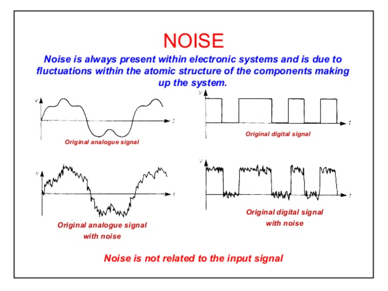
The image below shows how noise truly affects a signal (Vacchiano, 2019). The two graphs below show no noise and the graphs are smooth and very constant. The top right graph shows the constant voltage at the peaks of each rectangle. The bottom two graphs analyze the signals with noise introduced.
Image 1: Noise (Vacchiano, 2019).
It is clear to see that the constant value of the rectangles peaks is no longer constant as it fluctuates depending on how much noise is in the system. The rectangular graphs on the right of the image can represent digital signals where the peaks represent top logic 1 and bottom peaks represent logic 0. If the noise was strong enough it could cause logic 1 to possibly register as a logic 0 which will result in a transmission error if this was a communication system. This would not be efficient as people all over the world rely on efficient communications to properly transmit calls and texts.
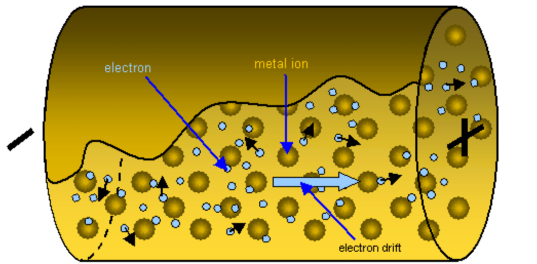
Noise that is generated from the circuit is caused by two main factors. One is electron flow, and the other is temperature. When a circuit is powered one current starts to flow in the direction of the higher potential to lower potential. The flow of the electrons is not straight as electrons bump into the circumference of the wire and each other (Keim, 2018). When this happens, the current will fluctuate depending on the interaction that occurs. The image below shows the electron flow through a wire (Electron Flow, n.d.).
Image 2: Electron Flow (Electron Flow, n.d.).
Looking at the black arrows on the electrons it is clear that they do not all travel in the same direction, but they all drift in the same direction. If each electron traveled in the same direction as the drift, then there would be a constant current, and no noise would be produced. Since they do not there are fluctuations in the current which results in fluctuations in voltage, generating noise. Controlling the flow of electrons to prevent these interactions is nearly impossible, which is one-way noise generated from a circuit.
Temperature fluctuations in a circuit generate something called thermal noise. Thermal noise is the result of several different conditions in a circuit. One way thermal noise is created is through the interaction of ions and electrons flowing in the circuit (Keim, 2018). The ions in the wire vibrate in their place and when electrons bump into the vibrating ions there is a transfer of energy (RF Thermal Noise, n.d.). The ion’s vibration rate is temperature-dependent, so the higher the temperature, the faster the vibrations, the bigger the thermal noise signal (RF Thermal Noise, n.d.). Thermal noise can have negative effects on electronics if ignored in the designing stage. It is impossible to eliminate thermal noise from electronics, but there are ways to reduce the effects of thermal noise. For these reasons, thermal noise has to also be considered when designing communication and audio circuits, as multiple internal and external factors can cause noise, or interfere with electronics. The goal of our innovation is to effectively reduce noise from several internal factors.
Existing Engineering Innovations
To prevent thermal noise from affecting circuits, electrical components are designed to operate at very low temperatures. Most modern-day electronics are not able to withstand changes from low to high temperatures, as condensation will form and short out the circuit. Also, at very low temperatures plastic parts of components can crack and break. Some companies produce components that can withstand low temperatures, circuits can be cooled to cryogenic temperatures to lower the resistance of wires in the circuit (Kirschman, 2009).
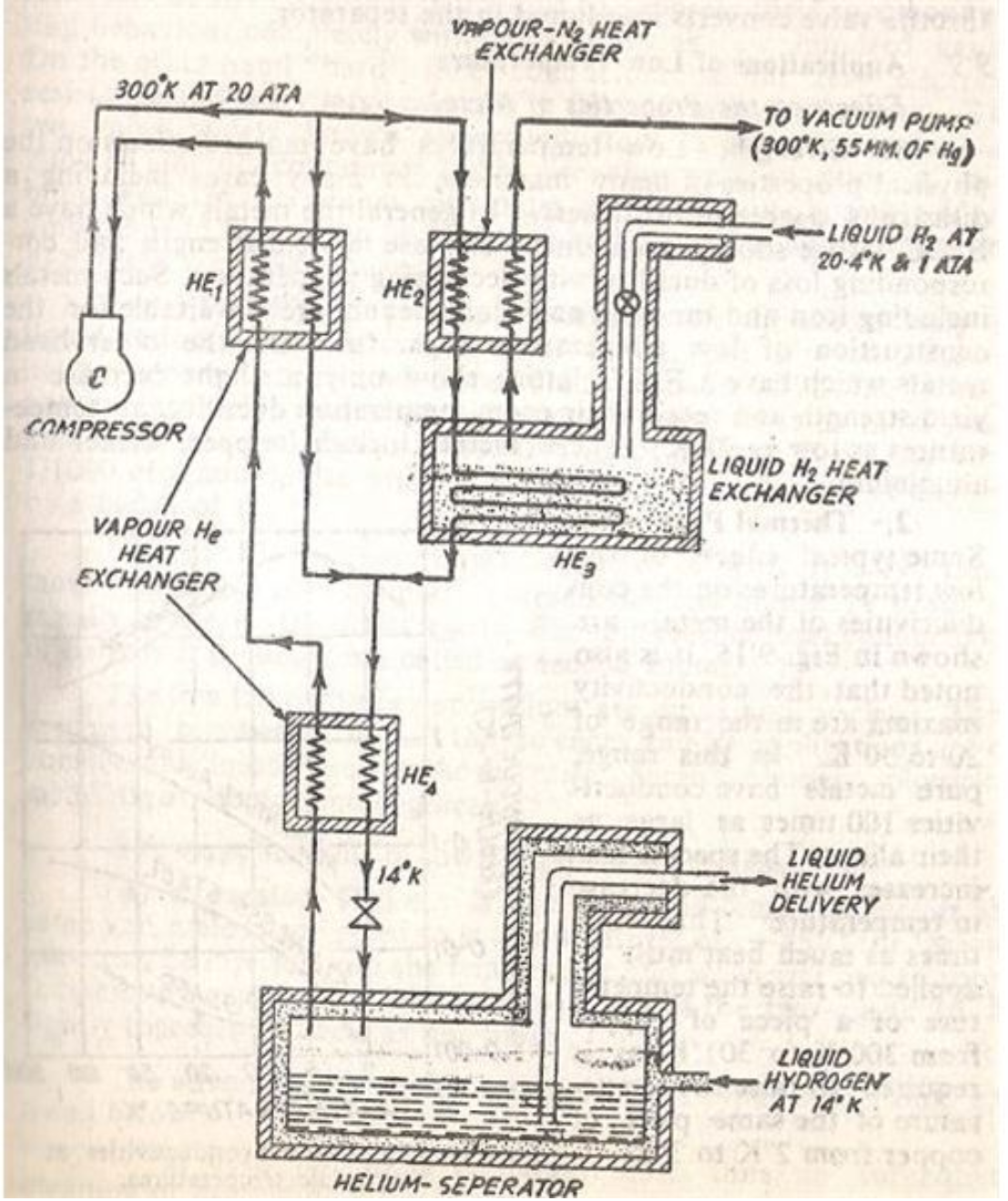
Having a lower resistance means the ions do not vibrate as fast as they normally would, and they release less energy when electrons flow into them. Liquid helium is used in cryogenic circuits but is hazardous as it can cause frostbite, burns, or death. Helium is a gas at room temperature, so the first step to turning it into a liquid is to compress helium to a suitable pressure for liquefying it (Helium Gas: Liquefaction of Helium. Applications of Helium, 2009). It is compressed to a pressure of 20 atmospheres (Helium Gas: Liquefaction of Helium. Applications of Helium, 2009). After being compressed the helium takes two paths (Helium Gas: Liquefaction of Helium. Applications of Helium, 2009). Both paths lead to heat exchangers, where the helium is initially cooled with the vapors of different gases. (Helium Gas: Liquefaction of Helium. Applications of Helium, 2009). One path uses Hydrogen vapors and then leads to another heating chamber where it is cooled again by liquid hydrogen (Helium Gas: Liquefaction of Helium. Applications of Helium, 2009). When the compressed Helium travels through the heat exchangers they exchange heat by contact with the gas or liquid they come into contact with. This way each time the helium passes through a heat exchanger it gets colder and colder. After the second path is cooled from the liquid helium it comes back to the first path and enters another heat exchange getting cooled even further by helium vapors (Helium Gas: Liquefaction of Helium. Applications of Helium, 2009). The final stage is known as a helium separator, where the gas is allowed to expand and pass through a value and become liquid helium (Helium Gas: Liquefaction of Helium. Applications of Helium, 2009). The process of converting the helium to its liquid is known as the Joule Thompson effect (Helium Gas: Liquefaction of Helium. Applications of Helium, 2009). The Joule Thompson effect states that if a gas is allowed to expand at constant volume and temperature, and then forced through a value the gas will be cooled, converting it to a liquid (The Editors of Encyclopaedia Britannica, n.d.). The diagram below shows the flow of the helium to turn it into a liquid.
Image 3: Liquefaction of Helium (Helium Gas: Liquefaction of Helium. Applications of Helium, 2009).
To control the temperature of the circuit, the circuit is placed inside the liquid helium, which will keep the circuit at cryo temperatures. Temperature-controlled cryogenic circuits can successfully reduce thermal noise, but it is not practiced for electronics such as phones and laptops (Kirschman, 2009). If a phone was dropped with liquid helium inside of it, it would be extremely dangerous if there was a leak of liquid helium. Also, there is no possible way to keep the helium at the necessary cryo temperature needed to reduce noise. For all of these reasons, our goal is to produce a portable, efficient, and temperature-effective way to prevent the temperature from creating noise in electronics.
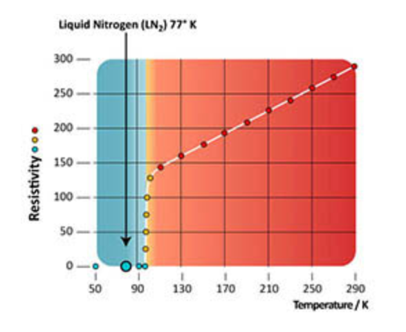
Superconducting wire can replace copper and if used at listed operating temperatures, can have zero resistivity. Superconductivity is when a material has no electrical resistance, allowing the flow of electrons (Ginsberg, n.d.). The temperature that superconductors operate on is usually -253 or lower (Ginsberg, n.d.). The highest temperature that these wires can operate on is -243.15 C (Superconducting-wire, 2019). The chart below shows the resistivity of the wire based on temperature.
Resistivity is a metal’s ability to allow electron flow throughout the metal (Resistivity, 2021). A metal with a high resistivity would make a better insulator than a conductor, and a metal with a lower resistivity would make a better conductor than an insulator. The chart below shows that at 90 degrees K, or -183.15 C the resistivity of superconducting wire is 0, meaning electrons will be able to flow with no resistance, resulting in fewer current fluctuations. This will provide more stable voltages and less noise. The problem with using superconducting wire is maintaining the temperature necessary for the wire to be a superconductor, and have no resistivity.
Our New Innovation
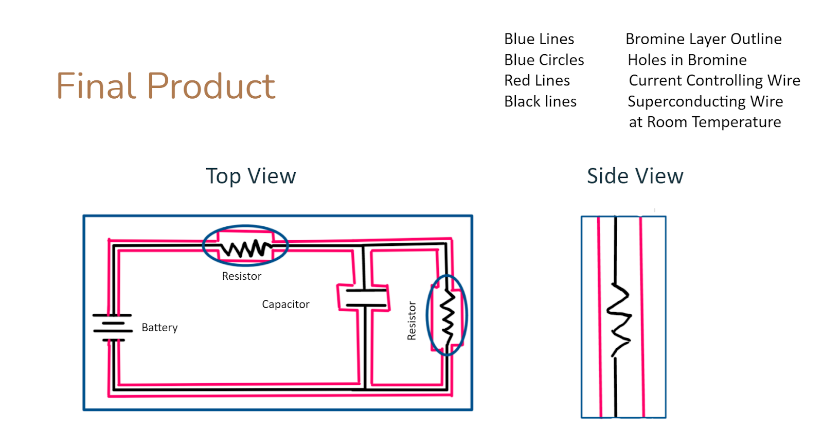
To reduce thermal noise and prevent portable liquid helium cooling systems high-temperature superconducting wire plus a temperature-controlled system would allow for most thermal noise to be eliminated. Being able to design a superconducting wire that would be able to have zero resistivity at room temperature would nearly eliminate thermal noise from electron flow through the wires. Most electronics have internal cooling fans to keep the components from overheating. To prevent massive fluctuations in temperature we aim to have our circuits sit inside a gel-like substance of bromine. Bromine was chosen as an insulator, not a conductor, and it will not produce shorts (Technical data for Bromine, n.d). The melting point of bromine is low so it will not melt and become a liquid and the boiling point is high and will not turn into a gas (Technical data for Bromine, n.d). The goal of the bromine is to control and absorb the thermal energy released from the circuit and maintain a stable temperature throughout the circuit. There will be several holes placed in the bromine to allow some heat to escape without being absorbed to prevent the bromine from transferring the heat back into the circuit. The image below shows liquid silicone is used to cover the circuit. Our process with bromine would look the same as the liquid silicone, except there would be holes for heat control and flow. The role of the bromine is not only to absorb heat but also to control heat flow to allow heat to escape the circuit. The combination of the bromine and the high-temperature superconducting wire would be able to effectively reduce thermal noise.
Imagine 5: Combination of Bromine and Wire (Adhesives and Silicones for Engineering Production, 2021)
To attempt the control of electron flow, there will be 4 wires surrounding the wire used in the circuit. in these four wires will be protons and electrons placed in specific places with specific charges. Electrons and protons attract each other, while electrons repel each other.
Image 6: Basic nature of charges (Basic Properties of Electric Charge, n.d.).
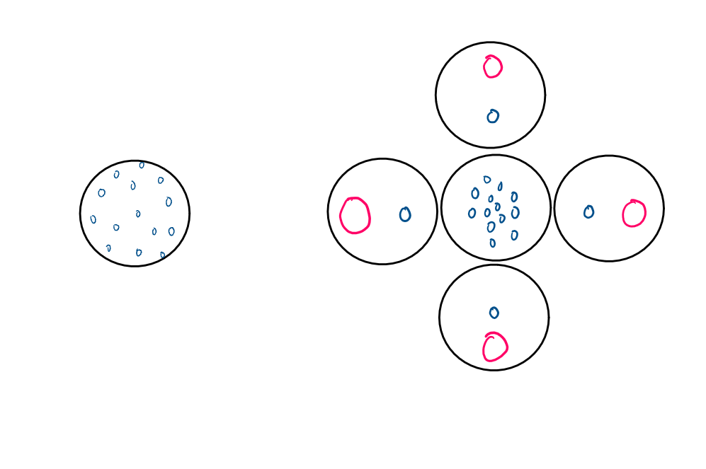
The chart above shows the direction of forces due to differently charged particles being placed near each other (Basic Properties of Electric Charge, n.d.). Also depending on the amount of charge on the electrons or protons the attraction or repelling forces will be stronger or weaker. If two electrons of the same charge are placed within a small distance of each other they will have the same repelling force in the direction of the opposite electron. If there is another set of two electrons placed at the same distance as the previous two electrons, except one electron has twice the charge of the other electron, the repelling force will be two times larger than the repelling force for the electron with the smaller charge. By placing the wires in a square equidistant from each other and surrounding the current wire will allow the placement of the electrons in the wires of the circuit. By changing the charge, some of the protons or electrons in the surrounding wire can change the placement of electrons as they would repel or attract to one side more. The image below shows a cross-section of two different types of wire. The one on the left is just a single wire, while the one on the right is a single wire surrounded by our four wires containing specifically placed protons and electrons. The blue circles represent electrons while the red ones represent protons.
Image 7: Cross Section of Wires
It is clear to see that the wire that has the four surrounding wires allows for better electron flow. The charges and the well-placed positions of the protons and electrons in those wires allow the electrons to stay more packed towards the middle of the wire, preventing them from bumping into the edge of the wire, therefore producing less noise. The combination of extra wires, bromine containment, and superconducting wires will reduce and eliminate some noise from electronic networks. Below is a diagram of our final product.
The Cost of Our Innovation
The cost of the extra wire would range from 8-12 dollars per foot. Most copper wires depending on gauge range from .07 cents a foot to .70 cents afoot. Our design involves 4 extra wires, plus we would have to manipulate the changes inside each wire. The cost of bromine is $5 for 100 grams, so assuming each circuit has about the same amount of bromine each circuit will use about 12-15 dollars’ worth of bromine. This is just the cost of materials, as we would have to have a team of engineers carefully lay out the bromine onto the circuit and add and replace electric wiring. The salary of these engineers would range from 90,000 – 120,000 a year. Depending on the amount of demand we would have anywhere from 10-30 engineers. Our company does not produce circuits but only would add extra materials to eliminate noise from circuits submitted to us. The turnaround time for our noise reduction techniques would be two weeks. Selling our techniques for $350 a circuit, and assuming 5500 circuits a year would put our cost of materials at $126,000 a year, the cost of salary for 10 engineers at $100,000 each would be $1,000,000 a year. Our sales would be $1,799,000, leaving us with a profit of $800,000 a year assuming no extra costs, or losses.
Conclusion
In conclusion, the goal of our innovation is that it will be successful in eliminating electronic noise from communication and audio electronics, with the hopes of it being highly sought after by large companies such as Beats, Boss, Bose, and radio station companies. We want to help consumers receive the best audio quality possible, and aspire to be the founding foundation of future innovations that further eliminate electronic noise from future electronic systems. To ensure your electronic device lasts to its longevity.
The lab report I decided to analyze is “Fabrication of bioactive composite scaffolds by electrospinning for bone regeneration” by Anandkumar Nandakumar, Hugo Fernandes, Jan de Boer, Lorenzo Moroni, Pamela Habibovic, and Clemens A. van Blitterswijk. This lab report is from the MEDLINE complete database and was published on August 26th, 2010. This lab report shows the process researchers took to help with the development of bone regeneration using different types of electrospun bioactive chemicals. This lab report includes the 8 basic elements to a lab report which are title, abstract, introduction, materials and methods, results, discussion, conclusion, and references.
The title of a lab report “should be informative enough to enable readers to decide whether the report interests them” (Markel & Selber, 2017). The title for this lab report is very clear on what the area of research is and has common terms like bone regeneration and electrospinning. These terms allow incoming readers to see if this report is in their area of interest. This is very useful to a lab report because it makes it easier for people to search the terms they want to research, which then directs them to report’s that include those terms.
The abstract to a lab report should always summarize the entire report and also have the structure of the report. Each part of the lab, introduction, methods, results, discussion, and conclusion, are briefly summarized (Markel & Selber, 2017). This report’s abstract, briefly explains the processes they took for this experiment. It also gives us a summary of the results found from day 4 and day 6. Then it gives us a short concussion as to how this experiment will be beneficial to bone regeneration. This lab’s abstract is very informative and shows the major findings in the research, which is more attractive to the readers (Markel & Selber, 2017).
The introduction of this lab follows the structure by “describing the hypothesis or question your study attempted to address and why this question is significant”(Markel & Selber, 2017). This hypothesis this lab provides is that “Combining collagen and HA is, therefore, a logical step toward creating scaffolds for bone regeneration” (Nandakumar, 2010). The introduction for this lab report also follows an example of how it “should include a concise review of previous research relevant to your study and should describe how your study extends the knowledge in your field or overcomes a weakness in previous studies” (Markel & Selber, 2017). This particular study shows a previous study about how researchers found it difficult to maintain electrospinning above a 20% weight percentage because of the “ineffective distribution of HA by the collagen” (Nandakumar, 2010). Then the introduction offers a solution to this problem which will be conducted in this experiment. The solution shown in this study is to either cross-linking the collagen or by combining it with another synthetic polymer (Nandakumar, 2010). By showing a solution to a previous study shows the significance to this study because it provides new information to this particular area of study. The introduction should also define important terms used in the experiment which is also done in this lab report in the very beginning.
The materials and methods part of a lab report should start with a list of materials used for the experiment (Markel & Selber, 2017). In this lab report, the materials and methods section was named the experimental part. The experimental part includes a list of materials and also gives credit to companies that have provided some of the materials. After listing the materials this section should provide the procedures used for the experiment (Markel & Selber, 2017). This lab report does this by providing information about how the solutions were prepared and the temperatures they were kept at. Then it provides a chronological step process the researchers took to conduct this experiment. By providing full details on how they did each step will help readers to fully understand what the experimental process was for the experiment. This is very crucial to the lab report because “your credibility rests on your ability to explain clearly what you did and why” (Markel & Selber, 2017).
The results of the lab report should present the evidence used to support the claims that will be made in the discussion (Markel & Selber, 2017). This part of the lab report will provide raw data found during the experiment. This is shown in this lab report through graphs and pictures of the outcome of the experiment. Each of the graphs also has a clear description of what the data is showing. It also provides an understanding of the major trends being shown in each of the graphs and pictures. The data then should also be referred to in the text and explain why it is significant to this experiment, which this lab report does by going over how these findings will be relevant to bone regeneration for humans. These elements are important because they will decide “how persuasive this evidence depends on how successfully you present it to your readers” (Markel & Selber, 2017).
The discussion part of a lab report is meant to either support or argue against the proposed hypothesis of the experiment. In this particular lab, the discussion does support the hypothesis of the experiment, which is shown when the researchers stated that “our results demonstrate the potential advantages of using bioactive scaffolds mimicking the ECM physical and chemical cues for regeneration of bone tissue” (Nandakumar, 2010). The discussion also provides a failed experiment, “All groups generally displayed this trend except PA–HA–Col” (Nandakumar, 2010). This is very important in the discussion because it provides new knowledge to this field of study. They explain the outcomes of the experiments so readers can get a better understanding of what the data represents.
The conclusion of this lab is a very clear summary of the main details shown in the lab report. It starts with a quick sentence saying what the purpose of the research was and then is followed up with a summary of the results found from the experiment. Then it states the significance of the research being done. This conclusion follows the appropriate model for a lab report since it was only one paragraph and summarizes everything done in the report. After the conclusion, this lab report also provides all the references made in the report. It shows a list of references made in chronological order of when the reference was made.
This lab report was very effective in keeping the structure of the 8 basic elements to a lab report. The title of the lab is very clear on what it will be about, and the abstract summarizes the entire report chronologically. The introduction then explains what the experiment is for and its significance. The materials and methods part of the lab goes over the steps taken in the experiment and gives full detail on how they did it. The results are also in the lab which informs readers about what the finished results were from the experiment through graphs and images. These graphs are fully summarized and explained and also give the major trend that appears in them. In the discussion, this lab does not hesitate to share the failures of the experiment because it is very crucial for future researchers in this subject. The summary is very short and gives a quick summary of the entire report. This lab also gives all the references that they used in the lab in the end. I think this lab would have been better if there was a table that shows what all the abbreviations of the terms were because it was hard to follow along since there are many terms used in the text. Overall this lab does follow the 8 basic elements to a lab report and does so at a high level.
Citation:
Markel, M., & Selber, S. (2017). Technical Communication (12th ed.). Bedford/St. Martin’s.
Nandakumar, A. N., Fernandes, H. F., Boer, J. B., Moioni, L. M., habibovic, P. H., & Blitterswijk, C. B. (2010). Fabrication of Bioactive Composite Scaffolds by Electrospinning for Bone Regeneration. https://onlinelibrary-wiley-com.ccny-proxy1.libr.ccny.cuny.edu/doi/full/10.1002/mabi.201000145#
Skateboarding is a sport where people ride a long wooden board with wheels. With these boards, the riders are able to perform various tricks with them. Although skateboarding is mostly for entertainment and doing tricks, it can also be used as a form of transportation.
There are two speculations in which ways that the first skateboard emerged. One way skateboards were invented was in the 1950s by surfers in California (Vee, 2020). These surfers wanted to experience surfing on the streets. This was called “sidewalk surfing” (Vee, 2020). Another way skateboard emerged was from kids changing the design of a scooter. These scooters were made out of a 2×4 birch plank with rollerskate wheels attached to it and had a milk crate standing at the top of the board which was used as a handle. Later kids would remove the milk crate and change the design to make the first skateboard (Vee, 2020).
Skateboards were first mass-produced by the company Roller Derby in 1959 (Vee, 2020).
Surfers would use [Figure 1.1 first Roller Derby skateboard ]
Pinterest. (n.d.). Pinterest. Retrieved March 20, 2021, from https://www.pinterest.ca/pin/807833251880687868/
this skateboard to practice their surfing skills when there weren’t many waves. Then in 1962 surf shops like “Val Suf” started selling complete skateboards with a more surfboard-like shape and trucks from rollerskates.
In that same year, a new company called “Patterson Forbs” made a more improved skateboard through upgraded trucks which helped with steering (Vee, 2020). This caused the first rise in the use of skateboards. However, the popularity of skateboarding peaked in 1963 because all the parts of the skateboard were low quality and there were no improvements made to the deck, wheels, or trucks (Vee, 2020).
Luckily in the 1970s, there was a breakthrough for skateboarding. The company called “Creative Urethane” created a new material called polyurethane (Vee, 2020). This material was repurposed by a guy named Frank Nasworthy, who asked the company to make wheels using polyurethane (Vee, 2020). He tested these wheels and discovered that it was smoother, there was more control and gained speed better than the metal and clay wheels that were used before (Vee, 2020). So Nasworthy made his own company called Cadillac Wheels Company and advertised these wheels toward skateboarding (Vee, 2020). This technological development reignited the popularity of skateboarding. Many companies now are innovating skateboards trying to make them more durable and reliable for skaters.
Skateboarding has always used plywood as the base of the skateboard since it was invented, but the shape of the board changed through the years. Many components of the skateboard like the wheels and trucks have been improved to make skateboards better.
Technical Description
Description
The Skateboard is a long narrow board that’s made out of plywood with a set of two wheels placed on both ends on the bottom of the board. The wheels are attached to a component called the truck which helps the rider steer the skateboard. The truck is held onto the plywood called the deck. The deck has a thing called griptape that’s glued to the top of the board. The rider stands on the board and propels himself forward by pushing their feet against the ground. The skateboard is sturdy enough to perform many tricks with it.
The deck is the base of the skateboard and is a wooden platform where the trucks are mounted at the bottom and the griptape is applied to the top. The front and back of the board, known as the nose and tail respectively, are concave and are raised slightly to make it more functional for the rider. Decks come in various sizes which is useful for people of different sizes, larger decks being more useful toward taller people and smaller decks for smaller people.
2. Griptape:
The griptape is a grainy, sandpaper-like sheet that is applied to the top of the deck so the skater doesn’t fall off the board. The griptape has an adhesive applied on the bottom so it can adhere to the deck before it’s assembled. It is used for traction and to control the skateboard.
3. Truck
The truck is a metal component of the skateboard that’s attached to both ends. This part is used to steer the skateboard when the person is riding by leaning to the left or right.
4. Riser
A riser is a durable plastic plate that sits between the truck and deck which elevates the skateboard higher. This is used to prevent wheel bite, which is when the wheels touch the deck when turning.
5. Wheels
There are 4 wheels on a skateboard and are made up of plastic polyurethane. There are two types of wheels, soft and hard wheels, which are used for different types of terrain. They also come in different sizes,
smaller and hard wheels are for street skateboarding while larger wheels and soft wheels are for cruising. The wheels have a hole in the middle where the bearings are placed.
6. Bearings
There are 8 total bearings used to make a skateboard, two on each side of each wheel. Bearings are metal rings with 8 small steel balls inside of them. This helps the wheels spin smoothly on the axles of the trucks.
7. Truck Bolts
Truck bolts are what attach the truck to the deck. There are 2 sets of 4 holes on the skateboard where the bolts attach the truck to the deck.
Conclusion
The skateboard has gone through many stages of development throughout its lifetime. It started as a scooter that kids played with to a sport that is played throughout the world. The popularity of skateboarding has gone through ups and downs, but it eventually stayed up due to the advancement in the components of the skateboard. The invention of new material for the wheels started the massive increase in its popularity and helped other companies start to focus on making improvements to the skateboard.
I am reaching out to you to tell you more about myself and my future goals. I was born in Bangladesh and moved to New York when I was about 4 years old. Adjusting to the different cultures in America was very difficult. However, I was able to overcome the change and formed many memories from living here in America. I also gained many achievements and talents.
One of my greatest achievements was when I received a gold award for a music contest. Leading up to the contest there were many challenges I had to overcome. One challenge I had to overcome was not being able to play a part in the music. With the help of my teacher and my perseverance, I was able to master the difficult part of music through constant practice. This experience taught me that with effort and constant practice I can get good at something I once found difficult.
One talent I have is that I can skate. I first learned to skate when I was a junior in high school. The first time I started skating I wasn’t good at it, but I loved skating. It helped relieve stress. I also liked skating with my friends. After skating for about 6 months I got decent at it and I was able to perform several tricks. Skating is something I still love to do during my free time to either relieve some stress or to hang out with my friends.
I also want to tell you about an experience that was meaningful to me. The experience was when I first started helping my dad with work. Working with my dad helped me get a little closer to him. It also gave me a better understanding of what he has to go through every day when he goes to work. During this time I helped my dad fix lightbulbs and other things. I went to people’s homes and helped my dad do the wiring for lights or a ceiling fan. He showed me how he does it and once let me do it myself. This experience gave me a better idea of what I might want to do in the future. I liked helping my dad do some light electrical work which inspired me to pursue electrical engineering in college.
I plan on majoring in electrical engineering. I chose electrical engineering because I thought it was interesting when I first helped my dad with work. In the future, I want to start my own company. First I want to work for a company to gain a lot of experience and what to expect when running a company. Then I plan on doing self-work and building a company from there. Although it sounds simple I am certain it will be a very difficult task.
I want you to see me as a hard worker and motivated student. I want to learn many things in this class that can help me in the future. I am very excited to learn from you and what this class can teach me about engineering.
Need help with the Commons?
Email us at [email protected] so we can respond to your questions and requests. Please email from your CUNY email address if possible. Or visit our help site for more information:

 helium to turn it into a liquid.