
Technical Description: Removal of Electronic Noise
MD Miah, James Bueno, Nissan Nath, & Christopher Guastella
Writing For Engineering
Professor Von Uhl
May 14, 2021
Table of contents:
~Introduction _____________________________________________________Page 3
~ Existing Engineering Inovations ____________________________________________________Page 5
~ Our New Inovation ____________________________________________________ Page 9
~ The Cost of Our Inovation ____________________________________________________Page 12
~ Conclusion ___________________________________________________Page 13
~ Work Cited ___________________________________________________Page 14
Removal of Electronic Noise
Introduction
Noise in electronic systems can cause massive problems for audio and communication systems. Electronic noise can cause unwanted disturbances and can cause systems to fail. Electronic noise is a random signal with a constant fluctuating voltage that gets mixed with input and received signals. The fluctuating voltage can cause digital signals to contain errors, communication signals to be transmitted incorrectly, and audio signals to sound fuzzy. Noise can be caused by multiple different factors inside and outside of a circuit.
The image below shows how noise truly affects a signal (Vacchiano, 2019). The two graphs below show no noise and the graphs are smooth and very constant. The top right graph shows the constant voltage at the peaks of each rectangle. The bottom two graphs analyze the signals with noise introduced.
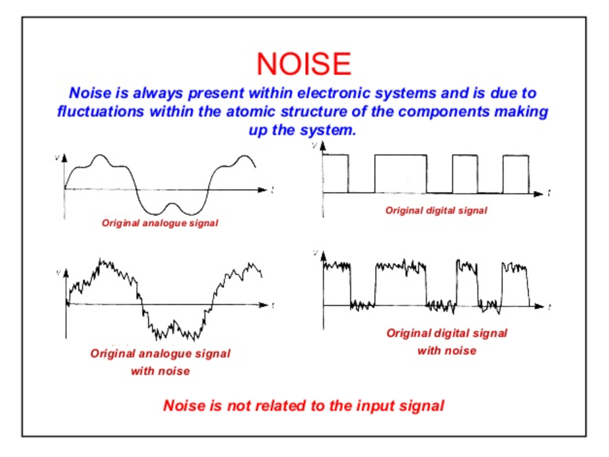
Image 1: Noise (Vacchiano, 2019).
It is clear to see that the constant value of the rectangles peaks is no longer constant as it fluctuates depending on how much noise is in the system. The rectangular graphs on the right of the image can represent digital signals where the peaks represent top logic 1 and bottom peaks represent logic 0. If the noise was strong enough it could cause logic 1 to possibly register as a logic 0 which will result in a transmission error if this was a communication system. This would not be efficient as people all over the world rely on efficient communications to properly transmit calls and texts.
Noise that is generated from the circuit is caused by two main factors. One is electron flow, and the other is temperature. When a circuit is powered one current starts to flow in the direction of the higher potential to lower potential. The flow of the electrons is not straight as electrons bump into the circumference of the wire and each other (Keim, 2018). When this happens, the current will fluctuate depending on the interaction that occurs. The image below shows the electron flow through a wire (Electron Flow, n.d.).
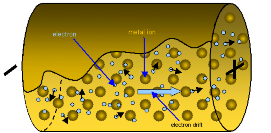
Image 2: Electron Flow (Electron Flow, n.d.).
Looking at the black arrows on the electrons it is clear that they do not all travel in the same direction, but they all drift in the same direction. If each electron traveled in the same direction as the drift, then there would be a constant current, and no noise would be produced. Since they do not there are fluctuations in the current which results in fluctuations in voltage, generating noise. Controlling the flow of electrons to prevent these interactions is nearly impossible, which is one-way noise generated from a circuit.
Temperature fluctuations in a circuit generate something called thermal noise. Thermal noise is the result of several different conditions in a circuit. One way thermal noise is created is through the interaction of ions and electrons flowing in the circuit (Keim, 2018). The ions in the wire vibrate in their place and when electrons bump into the vibrating ions there is a transfer of energy (RF Thermal Noise, n.d.). The ion’s vibration rate is temperature-dependent, so the higher the temperature, the faster the vibrations, the bigger the thermal noise signal (RF Thermal Noise, n.d.). Thermal noise can have negative effects on electronics if ignored in the designing stage. It is impossible to eliminate thermal noise from electronics, but there are ways to reduce the effects of thermal noise. For these reasons, thermal noise has to also be considered when designing communication and audio circuits, as multiple internal and external factors can cause noise, or interfere with electronics. The goal of our innovation is to effectively reduce noise from several internal factors.
Existing Engineering Innovations
To prevent thermal noise from affecting circuits, electrical components are designed to operate at very low temperatures. Most modern-day electronics are not able to withstand changes from low to high temperatures, as condensation will form and short out the circuit. Also, at very low temperatures plastic parts of components can crack and break. Some companies produce components that can withstand low temperatures, circuits can be cooled to cryogenic temperatures to lower the resistance of wires in the circuit (Kirschman, 2009).
Having a lower resistance means the ions do not vibrate as fast as they normally would, and they release less energy when electrons flow into them. Liquid helium is used in cryogenic circuits but is hazardous as it can cause frostbite, burns, or death. Helium is a gas at room temperature, so the first step to turning it into a liquid is to compress helium to a suitable pressure for liquefying it (Helium Gas: Liquefaction of Helium. Applications of Helium, 2009). It is compressed to a pressure of 20 atmospheres (Helium Gas: Liquefaction of Helium. Applications of Helium, 2009). After being compressed the helium takes two paths (Helium Gas: Liquefaction of Helium. Applications of Helium, 2009). Both paths lead to heat exchangers, where the helium is initially cooled with the vapors of different gases. (Helium Gas: Liquefaction of Helium. Applications of Helium, 2009). One path uses Hydrogen vapors and then leads to another heating chamber where it is cooled again by liquid hydrogen (Helium Gas: Liquefaction of Helium. Applications of Helium, 2009). When the compressed Helium travels through the heat exchangers they exchange heat by contact with the gas or liquid they come into contact with. This way each time the helium passes through a heat exchanger it gets colder and colder. After the second path is cooled from the liquid helium it comes back to the first path and enters another heat exchange getting cooled even further by helium vapors (Helium Gas: Liquefaction of Helium. Applications of Helium, 2009). The final stage is known as a helium separator, where the gas is allowed to expand and pass through a value and become liquid helium (Helium Gas: Liquefaction of Helium. Applications of Helium, 2009). The process of converting the helium to its liquid is known as the Joule Thompson effect (Helium Gas: Liquefaction of Helium. Applications of Helium, 2009). The Joule Thompson effect states that if a gas is allowed to expand at constant volume and temperature, and then forced through a value the gas will be cooled, converting it to a liquid (The Editors of Encyclopaedia Britannica, n.d.). The diagram below shows the flow of the 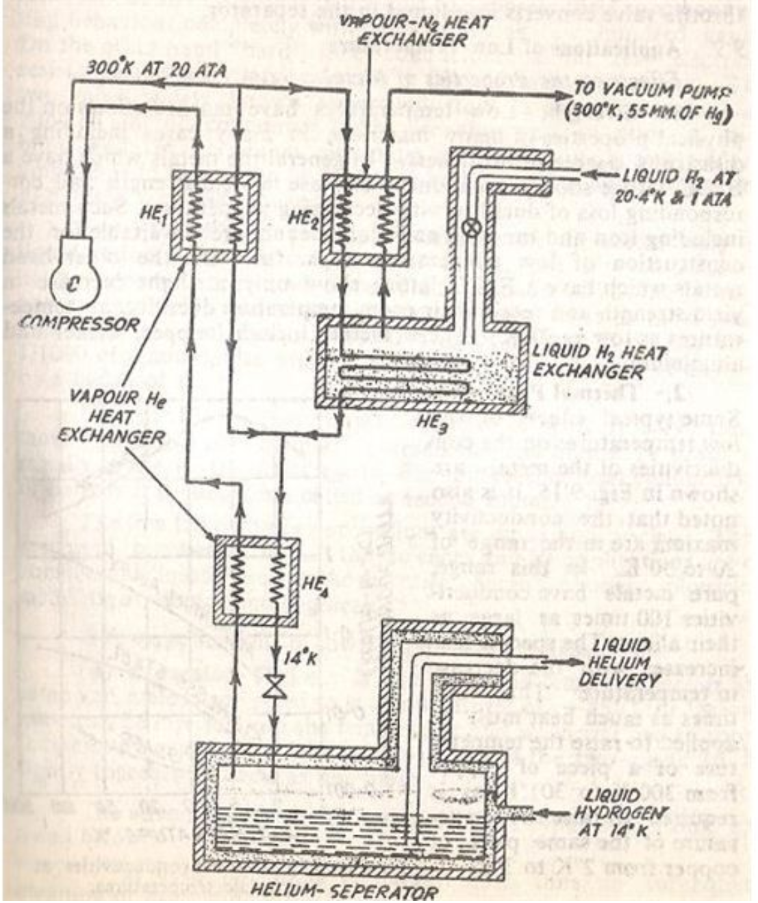
Image 3: Liquefaction of Helium (Helium Gas: Liquefaction of Helium. Applications of Helium, 2009).
To control the temperature of the circuit, the circuit is placed inside the liquid helium, which will keep the circuit at cryo temperatures. Temperature-controlled cryogenic circuits can successfully reduce thermal noise, but it is not practiced for electronics such as phones and laptops (Kirschman, 2009). If a phone was dropped with liquid helium inside of it, it would be extremely dangerous if there was a leak of liquid helium. Also, there is no possible way to keep the helium at the necessary cryo temperature needed to reduce noise. For all of these reasons, our goal is to produce a portable, efficient, and temperature-effective way to prevent the temperature from creating noise in electronics.
Superconducting wire can replace copper and if used at listed operating temperatures, can have zero resistivity. Superconductivity is when a material has no electrical resistance, allowing the flow of electrons (Ginsberg, n.d.). The temperature that superconductors operate on is usually -253 or lower (Ginsberg, n.d.). The highest temperature that these wires can operate on is -243.15 C (Superconducting-wire, 2019). The chart below shows the resistivity of the wire based on temperature.
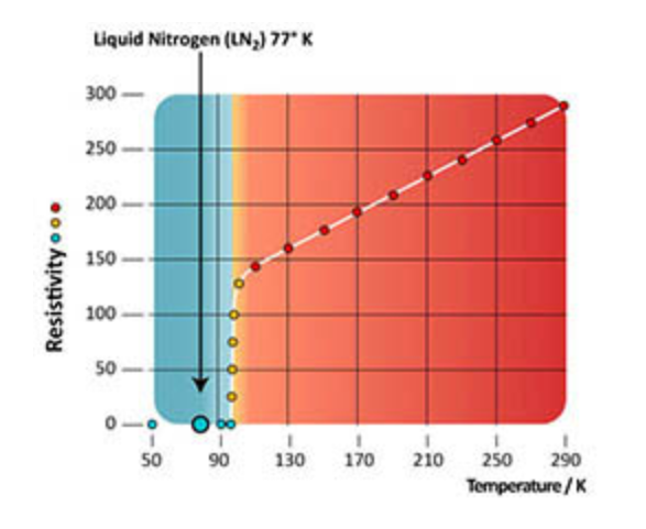
Image 4: Resistivity (Superconducting-wire, 2019).
Resistivity is a metal’s ability to allow electron flow throughout the metal (Resistivity, 2021). A metal with a high resistivity would make a better insulator than a conductor, and a metal with a lower resistivity would make a better conductor than an insulator. The chart below shows that at 90 degrees K, or -183.15 C the resistivity of superconducting wire is 0, meaning electrons will be able to flow with no resistance, resulting in fewer current fluctuations. This will provide more stable voltages and less noise. The problem with using superconducting wire is maintaining the temperature necessary for the wire to be a superconductor, and have no resistivity.
Our New Innovation
To reduce thermal noise and prevent portable liquid helium cooling systems high-temperature superconducting wire plus a temperature-controlled system would allow for most thermal noise to be eliminated. Being able to design a superconducting wire that would be able to have zero resistivity at room temperature would nearly eliminate thermal noise from electron flow through the wires. Most electronics have internal cooling fans to keep the components from overheating. To prevent massive fluctuations in temperature we aim to have our circuits sit inside a gel-like substance of bromine. Bromine was chosen as an insulator, not a conductor, and it will not produce shorts (Technical data for Bromine, n.d). The melting point of bromine is low so it will not melt and become a liquid and the boiling point is high and will not turn into a gas (Technical data for Bromine, n.d). The goal of the bromine is to control and absorb the thermal energy released from the circuit and maintain a stable temperature throughout the circuit. There will be several holes placed in the bromine to allow some heat to escape without being absorbed to prevent the bromine from transferring the heat back into the circuit. The image below shows liquid silicone is used to cover the circuit. Our process with bromine would look the same as the liquid silicone, except there would be holes for heat control and flow. The role of the bromine is not only to absorb heat but also to control heat flow to allow heat to escape the circuit. The combination of the bromine and the high-temperature superconducting wire would be able to effectively reduce thermal noise.
Imagine 5: Combination of Bromine and Wire (Adhesives and Silicones for Engineering Production, 2021)

To attempt the control of electron flow, there will be 4 wires surrounding the wire used in the circuit. in these four wires will be protons and electrons placed in specific places with specific charges. Electrons and protons attract each other, while electrons repel each other.

Image 6: Basic nature of charges (Basic Properties of Electric Charge, n.d.).
The chart above shows the direction of forces due to differently charged particles being placed near each other (Basic Properties of Electric Charge, n.d.). Also depending on the amount of charge on the electrons or protons the attraction or repelling forces will be stronger or weaker. If two electrons of the same charge are placed within a small distance of each other they will have the same repelling force in the direction of the opposite electron. If there is another set of two electrons placed at the same distance as the previous two electrons, except one electron has twice the charge of the other electron, the repelling force will be two times larger than the repelling force for the electron with the smaller charge. By placing the wires in a square equidistant from each other and surrounding the current wire will allow the placement of the electrons in the wires of the circuit. By changing the charge, some of the protons or electrons in the surrounding wire can change the placement of electrons as they would repel or attract to one side more. The image below shows a cross-section of two different types of wire. The one on the left is just a single wire, while the one on the right is a single wire surrounded by our four wires containing specifically placed protons and electrons. The blue circles represent electrons while the red ones represent protons.
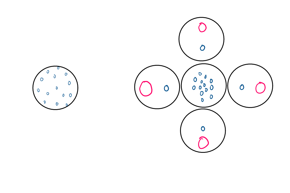
Image 7: Cross Section of Wires
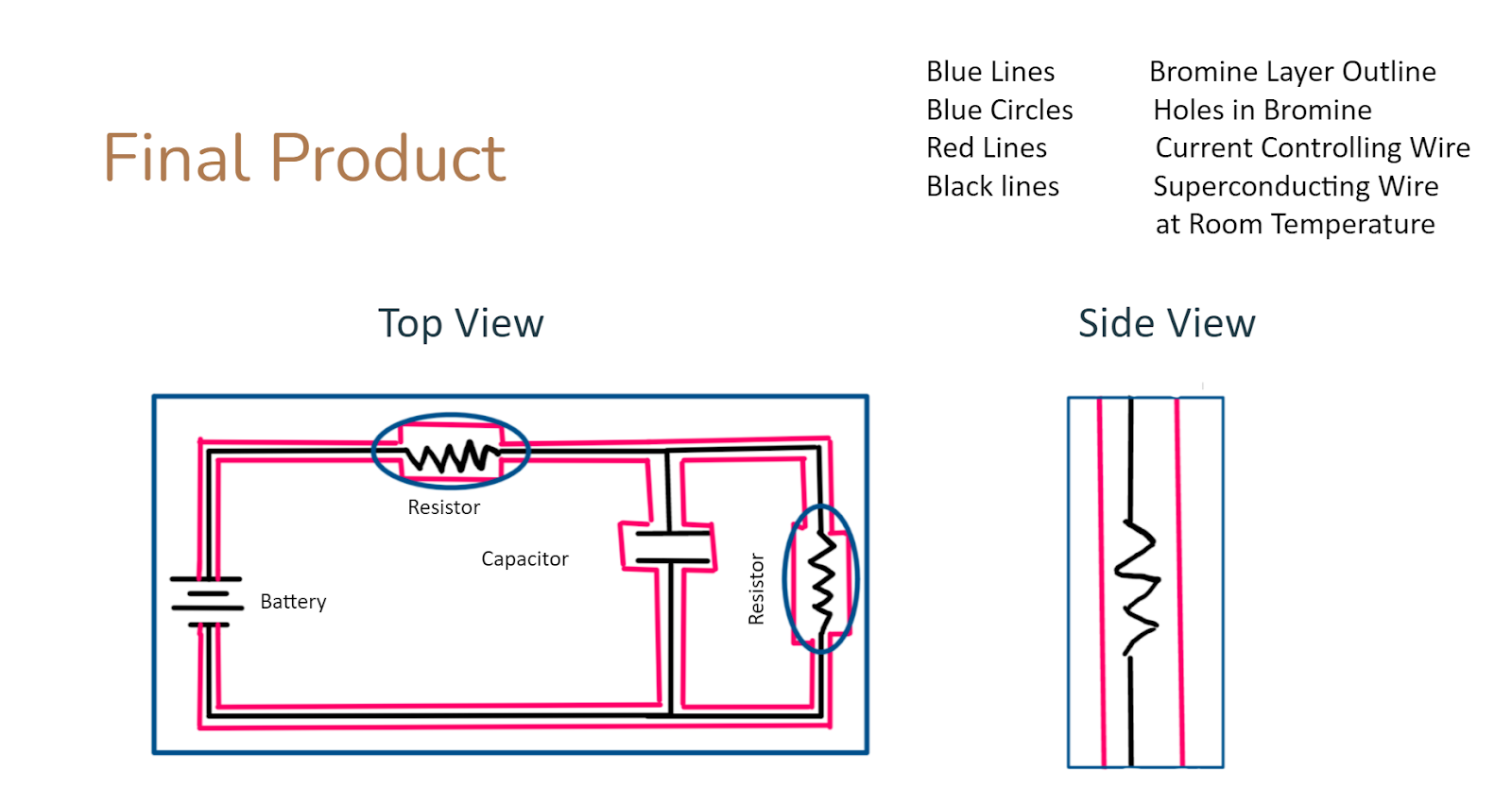
It is clear to see that the wire that has the four surrounding wires allows for better electron flow. The charges and the well-placed positions of the protons and electrons in those wires allow the electrons to stay more packed towards the middle of the wire, preventing them from bumping into the edge of the wire, therefore producing less noise. The combination of extra wires, bromine containment, and superconducting wires will reduce and eliminate some noise from electronic networks. Below is a diagram of our final product.
The Cost of Our Innovation
The cost of the extra wire would range from 8-12 dollars per foot. Most copper wires depending on gauge range from .07 cents a foot to .70 cents afoot. Our design involves 4 extra wires, plus we would have to manipulate the changes inside each wire. The cost of bromine is $5 for 100 grams, so assuming each circuit has about the same amount of bromine each circuit will use about 12-15 dollars’ worth of bromine. This is just the cost of materials, as we would have to have a team of engineers carefully lay out the bromine onto the circuit and add and replace electric wiring. The salary of these engineers would range from 90,000 – 120,000 a year. Depending on the amount of demand we would have anywhere from 10-30 engineers. Our company does not produce circuits but only would add extra materials to eliminate noise from circuits submitted to us. The turnaround time for our noise reduction techniques would be two weeks. Selling our techniques for $350 a circuit, and assuming 5500 circuits a year would put our cost of materials at $126,000 a year, the cost of salary for 10 engineers at $100,000 each would be $1,000,000 a year. Our sales would be $1,799,000, leaving us with a profit of $800,000 a year assuming no extra costs, or losses.
Conclusion
In conclusion, the goal of our innovation is that it will be successful in eliminating electronic noise from communication and audio electronics, with the hopes of it being highly sought after by large companies such as Beats, Boss, Bose, and radio station companies. We want to help consumers receive the best audio quality possible, and aspire to be the founding foundation of future innovations that further eliminate electronic noise from future electronic systems. To ensure your electronic device lasts to its longevity.
Work Cited
Adhesives and Silicones for Engineering Production. APPLIED Adhesives. (2021, May 7). https://www.appliedadhesives.com/solutions/engineering-tech-and-silicones/.
Basic Properties of Electric Charge. (n.d.). AskiiTians. Retrieved May 4, 2021, from https://www.askiitians.com/iit-jee-electrostatics/basic-properties-of-electric-charge/
Ginsberg, D. M. (n.d.). Superconductivity. Encyclopedia Britannica. Retrieved May 3, 2021, from https://www.britannica.com/science/superconductivity
Helium Gas: Liquefaction of Helium. Applications of Helium. (2009, January 24). Bright Hub Engineering. https://www.brighthubengineering.com/hvac/23777-liquefaction-of-helium/
Keim, R. (2018, June 21). What Is Electrical Noise and Where Does It Come From? AllAboutCircuits. https://www.allaboutcircuits.com/technical-articles/electrical-noise-what-causes-noise-in-electrical-circuits/
Kirschman, R. (2009, November 5). Cryogenic Electronics. Cryogenic Society of America. https://cryogenicsociety.org/resources/cryo_central/cryogenic_electronics/#:%7E:text=Semiconductor-based%20cryogenic%20electronics%20can%20be%20as%20simple%20as,in%20power%20from%20microwatts%20to%20hundreds%20of%20watts
Resistivity. (n.d.). Encyclopedia Britannica. Retrieved May 3, 2021, from https://www.britannica.com/science/resistivity
RF Thermal Noise | Johnson-Nyquist Noise | Electronics Notes. (n.d.). RF Thermal Noise: Johnson-Nyquist Noise. Retrieved May 3, 2021, from https://www.electronics-notes.com/articles/basic_concepts/electronic-rf-noise/thermal-johnson-nyquist-basics.php#:%7E:text=Thermal%20noise%20is%20always%20present%20in%20electronic%20circuits,design%20parameters.%20Noise%20as%20seen%20on%20an%20oscilloscope
schoolphysics ::Welcome:: (n.d.). SchoolPhysics. Retrieved May 3, 2021, from https://www.schoolphysics.co.uk/age16-19/glance/Electricity%20and%20magnetism/Electron_flow/index.html
Superconducting-wire. (n.d.). SupTech. Retrieved May 3, 2021, from https://www.suptech.com/superconducting-wire/#:%7E:text=High%20Temperature%20Superconducting%20%28HTS%29%20Wire%20There%20are%20two,Barium%20-%20Copper%20Oxide%E2%80%9D%20for%20the%20superconducting%20compound.
Technical data for Bromine. Technical data for the element Bromine in the Periodic Table. (n.d.). https://periodictable.com/Elements/035/data.html
The Editors of Encyclopaedia Britannica. (n.d.). Joule-Thomson Effect. Encyclopedia Britannica. Retrieved May 3, 2021, from https://www.britannica.com/science/Joule-Thomson-effect
Vacchiano, M. (2019, September). FOTOGRAFIA NADIR MAGAZINE – ETTR, OVVERO ESPORRE A DESTRA. https://www.nadir.it/tecnica/ETTR_ESPORRE-A_DESTRA/ETTR.htm
Reflection: